Geometry Parameterization with ESP
Previous tutorials discussed parameterizing geometry with pyGeo through FFDs. pyGeo also supports parameterization with the Engineering Sketch Pad (ESP), an open-source CAD program. This page is intended to build on the previously presented pyGeo information to show how ESP can be used instead of FFDs. For information on how to install ESP and its dependencies for use in pyGeo, see the installation page.
The FFD approach is sometimes preferred because it is easy to set up and has a lot of freedom in how the design variables can change the geometry. Unfortunately, the FFD control points are the only representations of the geometry other than the mesh, which can make it hard to take an optimized result and use it. To avoid this, a CAD model can be used to parameterize the geometry instead of an FFD. This allows a single consistent format to represent the geometry throughout the optimization. The CAD model is used as an input, changed throughout the optimization, and then can be used as an output. This parameterization can take additional effort to set up but is sometimes preferred as it produces an output in a more traditional format useful in some applications.
Note
This tutorial is intended to only be a simple demonstration of how to use ESP with pyGeo. For information about more complex modeling in ESP, please see their documentation and tutorials.
Generating the ESP model
First, we will need to set up our ESP model with the parameterizations we will use later. Then we can add the corresponding design variables in our runscript.
ESP models are created in a plain text scripting language.
The full script for this model can be found at pygeo/examples/esp_airfoil/naca0012.csm but we will show portions here.
For this basic example, we will create a simple airfoil model.
First, we create our design variables, which are called DESPMTR (design parameter) in the ESP model.
Our design variables will be camber (called camber_dv), the location of max camber (maxloc_dv), and thickness (called thickness_dv in the script).
DESPMTR camber_dv 0.0
DESPMTR maxloc_dv 0.4
DESPMTR thickness_dv 0.12
Now we can use these design variables in another ESP feature, a UDPRIM or user-defined primitive.
The naca user-defined primitive will allow us to easily generate a NACA airfoil according to our design variables.
For more information on naca and other types of UDPRIM in ESP, see their documentation.
UDPRIM naca camber camber_dv maxloc maxloc_dv thickness thickness_dv
Because we need a 3D representation of an airfoil for most solvers, we will create another a second airfoil and use the BLEND command to create a shape between the two that does not change in the spanwise direction.
TRANSLATE 0 0 -0.2
UDPRIM    naca  camber camber_dv  maxloc maxloc_dv  thickness thickness_dv
TRANSLATE 0 0 1.2
BLEND
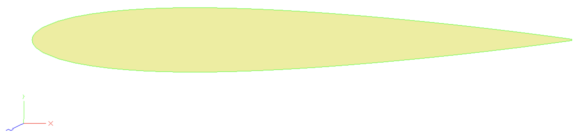
Opening the model in the ESP GUI, the side view of the airfoil should look as expected for a NACA 0012.
Parameterizing using pyGeo
Now that we have an ESP model, we need to load it into pyGeo and define how our optimizer, through pyGeo, can change and deform the geometry.
First we need to initialize our DVGeo object like in the FFD case, but this time it is a DVGeometryESP object, the class specialized to manipulate ESP models.
Like our previous DVGeo objects were initialized with FFD files, this is initialized with the script that contains our ESP model.
# initialize the DVGeometry object with the csm file
csm_file = "naca0012.csm"
DVGeo = DVGeometryESP(csm_file)
Just as in the FFD approach, a pointset is necessary for pyGeo to internally keep track of the geometry. We will again use an existing triangulated surface mesh to initialize the pointset.
stlmesh = mesh.Mesh.from_file("esp_airfoil.stl")
# create a pointset. pointsets are of shape npts by 3 (the second dim is xyz coordinate)
# already have the airfoil mesh as a triangulated surface (stl file)
# each vertex set is its own pointset, so we actually add three pointsets
DVGeo.addPointSet(stlmesh.v0, "mesh_v0")
DVGeo.addPointSet(stlmesh.v1, "mesh_v1")
DVGeo.addPointSet(stlmesh.v2, "mesh_v2")
Now we can add our design variables.
These names must correspond with the names we chose for the design parameters in our ESP model.
Here we will treat all three of our ESP design parameters as design variables in pyGeo, but we could have chosen a subset to add to our DVGeo object if we only wanted to modify camber and thickness for example.
# Now that we have pointsets added, we should parameterize the geometry.
# Adding geometric design variable to make modifications to the airfoil geometry directly
DVGeo.addVariable("camber_dv")
DVGeo.addVariable("maxloc_dv")
DVGeo.addVariable("thickness_dv")
Perturbing design variables
Now that our pointset, our ESP model, and our design variables are all tied together using pyGeo, we can perturb these design variables.
The code snippet below illustrates a few key methods of the public API.
Note that these are similar to the DVGeometry methods used in the FFD case, with the addition of a method to write our new ESP model.
writeCSMFilewrites a new ESP model with the updated design variable values.
# Perturb some local variables and observe the effect on the surface
dvdict = DVGeo.getDesignVars()
dvdict["camber_dv"] = 0.09
dvdict["maxloc_dv"] = 0.8
dvdict["thickness_dv"] = 0.2
DVGeo.setDesignVars(dvdict)

# write out the new ESP model
DVGeo.writeCSMFile("modified.csm")
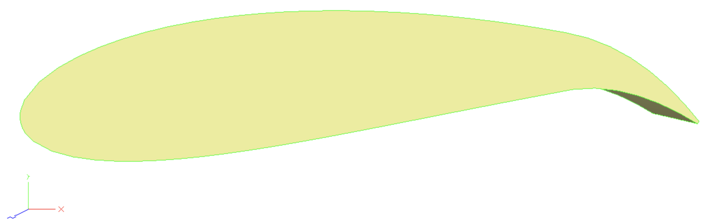
Now we can see the new script for the ESP model at pygeo/examples/esp_airfoil/modified.csm.
This can be loaded into the ESP GUI to see the effects of our changes to the design variables.
Summary
In this tutorial, you learned the basics of pyGeo’s ESP geometry parameterization capabilities. You now know enough to set up a basic shape optimization, such as the airfoil portion of the MACH-Aero tutorial.
The scripts excerpted for this tutorial are located at pygeo/examples/esp_airfoil/esp_airfoil.py and naca0012.csm.